SCANTRIC SMS
SCANTRIC MODBUS
SCANTRIC Repeater
Control the world from your cell phone...

SCANTRIC D86-M8 Data Acquisition Module
Scantric is the heart of an excellent price/performance SCADA system. It has:
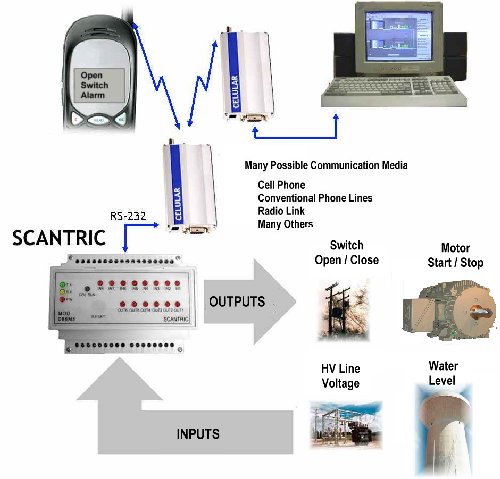
  • 8 analog or digital inputs
  • 6 open collector outputs
  • An RS-232 Serial Asynchronous communication port
  • Programmable parameters in non volatile memory

Scantric SMS Picture
Depending on the loaded firmware option, SCANTRIC modules can be polled by the control center using either MODBUS RTU or Cellular Short Message Service (SMS) communication protocol.
D86-M8-MODBUS option is intended to work as remote terminal unit (RTU) in conventional control center polled SCADA networks. The MODBUS protocol is one of the most widely used standards in automatic and distributed system communications.
D86-M8-SMS option allows to turn a cellular phone into a low cost control center. To accomplish this function, programmable messages are stored in the NV memory for later transmission of event information. Furthermore, the operator can send commands and poll any variables from the same cellular phone.
D86-M8-Repeater modules allow digital equipment (DTE) with no handshaking signals to control radio transceiver's PTT. They receive data from DTE then, after a programmed interval, They transmit this information through a radio channel. The time required for carrier stabilization before data transmission is also programmable.
With proper register settings and hardware connections, Repeater modules can also work as MODBUS units. When used in repeater mode, They lack MODBUS, data acquisition and remote control funtions.

Block Diagram
Applications


Download Presentation


PDF (0.9 MBytes)
MS Power Point (7.6 MBytes)
Video (1.5 MBytes)


Terminal Description
No. Function No. Function
1 Power Supply +Vcc 16 OC Output 5
2 Power Supply GND 17 OC Output 6
3 RTS 26 Input GND
4 RD 27 Input GND
5 DCD 28 Analog/Digital Input 1
6 TD 29 Analog/Digital Input 2
7 GND Output 30 Analog/Digital Input 3
10 Output GND 31 Analog/Digital Input 4
11 Output GND 32 Analog/Digital Input 5
12 OC Output 1 33 Analog/Digital Input 6
13 OC Output 2 34 Analog/Digital Input 7
14 OC Output 3 35 Analog/Digital Input 8
15 OC Output 4
Technical Specifications
Power Supply 10 - 24 Vdc
Consumption < 100 mA
Communication Port RS-232 Serial Asynchronous
Communication Protocols
  • D86-M8-MODBUS
  • D86-M8-Repeater (When
    not configured as repeater)
  • D86-M8-SMS
MODBUS RTU
MODBUS RTU

SMS
Operation Temperature -10ºC to 60ºC
Inputs 8
Input Voltage Level 0 - 5 V
Overall Analog Input Accuracy 0.5 %
Open Collector Oputputs 6
Maximun Output Sink 200 mA
Dimensions length x width x height =
105 x 90 x 70 mm
Mounting DIN rail
Visual Indications Eighteen 3mm leds (POWER, TX, RX, CPU RUN, INPUTS and OUTPUTS


www.atechna.com