
|
|
SCANTRIC LW |
|
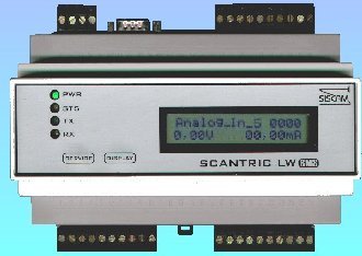
SCANTRIC LW Programmable Logic Controller
It is intended to perform a wide range of different tasks, such as analog measurement, remote control, switch closure detection, etc. However, in addition of these functions, its primary purpose is to communicate a local LonWorks technology based network with a MODBUS control center. | |
|
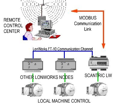
By example, consider the following case: There is a conventional MODBUS protocol based SCADA
network. It is required to install a new remote station. For convenience It is decided to take
advantage of LonWorks technology. A SCANTRIC LW module can play the role of a gateway to
make possible communication among the station's nodes and the Control Center. Simultaneously the
same module can monitor local variables and take over of remote command operations. MODBUS communication is accomplished by means of the module's serial port. The SCANTRIC-LW module also has a LonWorks FT-10 port to perform communication with other LonWorks nodes. SCANTRIC LW can be also polled by means of SMS (Short Message Service). This feature allows to turn a Cell Phone into a Control Center. For a small SCADA system this may be a convenient way to reduce equipment complexity and cost. Seven analog inputs are provided, They are voltage/current jumper selectable, 10 bit precision. SCANTRIC-LW has also 8 dry contact inputs and 8 open collector outputs. |
|
Applications
Telemetry and SCADA Systems
|
|
Technical Specifications
|
|||||||||||||||||||||||||||||||||||||||||||||||||||||||||||||||||||||||||||||||||||||||||||||||||||||||||||||||||||